EECS 270 Project 7: sequential four-function calculator in Verilog. Shared AddSub datapath, Booth-style multiply, magnitude divide, SM/TC conversion, ModelSim tests, and board I/O on switches, keys, and HEX displays.
- Stack
- VerilogFPGAModelSimFSMRTL
- Outcomes
DE2-115
Board
11-bit
Word width
+ − × ÷
Ops
- Highlights
- Datapath / controller split with one shared AddSub unit
- Booth multiply and magnitude divide with overflow / divide-by-zero
- Board demo — SW entry, KEY ops, HEX result, LEDG overflow
Gallery
Problem and outcome
Build a sequential calculator — not a one-cycle ALU. An FSM walks operands through add, subtract, multiply, and divide and shows a stable result on HEX.
Outcome: FourFuncCalc datapath + controller for 11-bit two’s-complement
arithmetic, with ModelSim coverage and a board demo.
Role
- Course: EECS 270, University of Michigan
- Spec: Project 7 — Sequential Calculator
- My work:
FourFuncCalc.v,TestBench7.v,Project7.vboard wiring
Architecture
SW / KEY / SW[17]  →  FourFuncCalc (FSM + datapath)
                         ├─ HEX operand / result
                         └─ LEDG[8] overflow / ÷0
Technical decisions
1. One shared AddSub for all four ops (required datapath).
2. Booth multiply embedded in the datapath (not a direct BoothMul instance).
3. Divide on magnitudes; sign via XOR; divisor zero → overflow until clear.
4. External signed-magnitude, internal two’s complement via staff converters.
Validation
ModelSim with state labels; autograder checkpoint (ADD/SUB) and final (all ops); board checks on DE2-115 / LabsLand.
Limitations
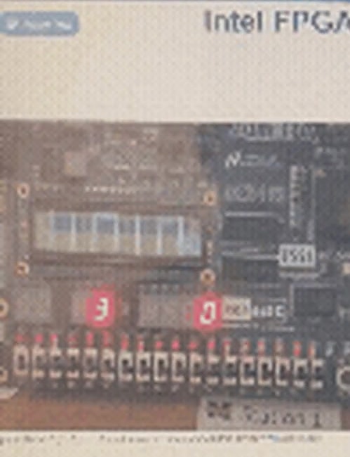
Cover is a frame from a soft LabsLand recording, not a sharp bench photo with a clearly readable result. Diagrams in the gallery are course-provided figures.